Can crusher driven by a standing-desk leg.
From an 80 kg desk leg to 1.8 kN of crushing force.
Try the mechanism
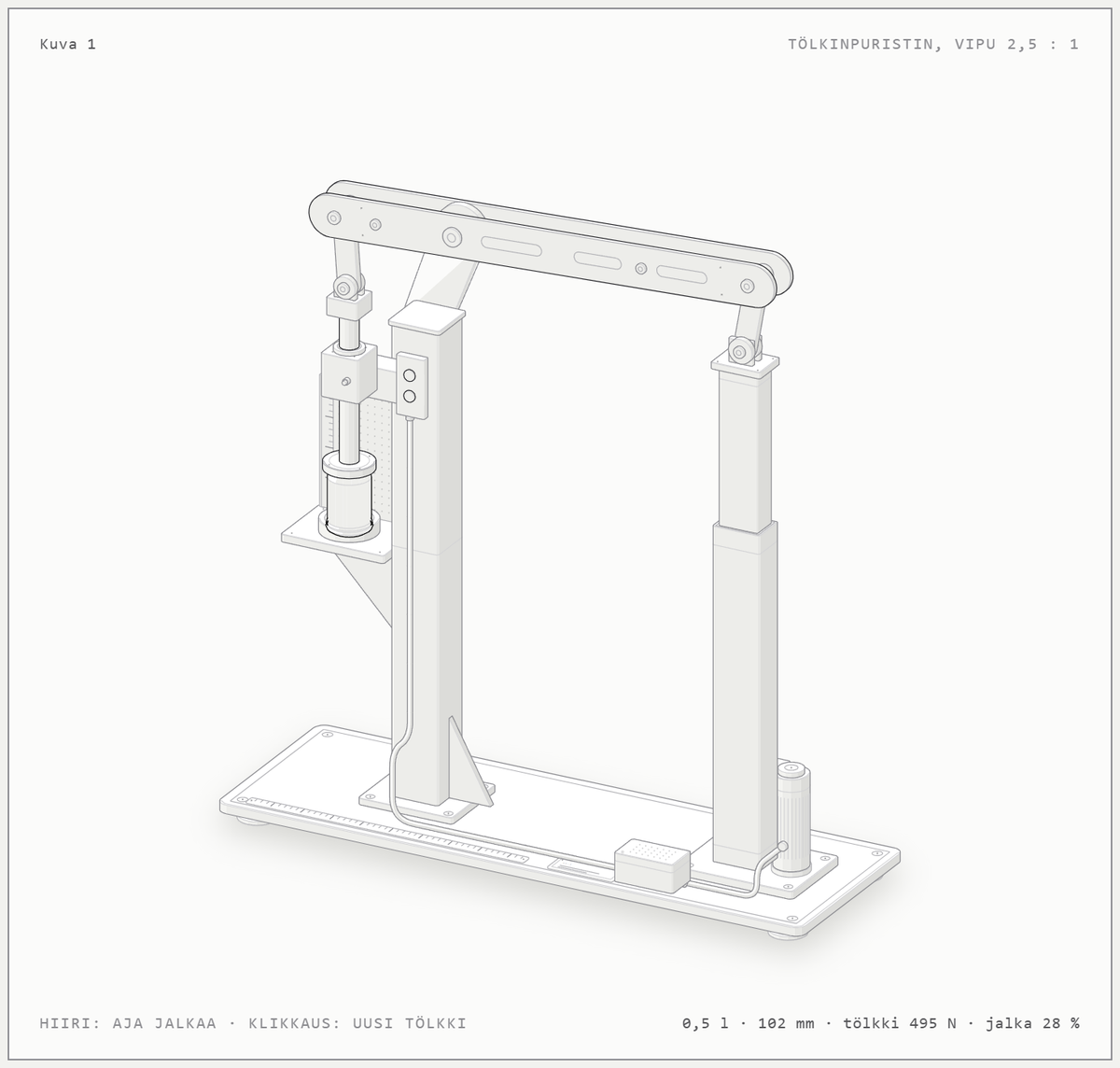
Move the pointer sideways over the figure to drive the desk leg. The readout shows the can’s resistance and how much of the leg’s force the crushing takes. Click to load a new can. Left alone, the figure runs a full cycle: crush, return and the flattened can dropping into the bin. The labels in the figure are in Finnish.
Starting point: one conversation with an AI
A friend asked for some mechanical design: his man cave needed a can crusher. I worked it through in a conversation with Claude. As input I gave only what we knew: there is the leg motor of an old standing desk, it pushes about 80 kg, and a lever might multiply the force. We had no detailed specifications for the leg, and we did not know how much force crushing a can takes.
The AI found the missing data
Claude searched the web for comparable desk legs: 80 kg is about 785 N, speed under load 25–40 mm/s, a typical stroke of 500–650 mm and a duty cycle of about 10%. It also looked up research on the axial loading of beverage cans. The conclusion was clear: an intact can withstands an estimated 1.0–1.5 kN before it first buckles, so the leg alone would stall right at the start.
The AI invented and sized the mechanism
Claude proposed the mechanism itself and calculated the lever ratios. It rejected 2:1 as too tight, since the leg would be at about 92% load at the peak, and chose 2.5:1, which puts about 1.8 kN on the can. The first version was a floor-standing vertical press: a seesaw lever pivoting on top of a column, with 200 and 500 mm arms. Links take up the lever’s arc and the ram runs in bronze bushings. It sized the flat bars, pins and column with rough strength calculations.
A second conversation: the wall model
Then I asked briefly: what if the crusher were wall-mounted and the flattened can dropped into a bin by gravity? Claude redesigned the mechanism. In a vertical press the puck would stay on the base plate, so it turned the ram horizontal and replaced the straight lever with a bell crank that turns the leg’s vertical motion into horizontal motion at the same 2.5:1 ratio. The can lies in a trough, and next to the end plate is a 42 mm slot: an intact can is longer than the slot and stays put, while a puck flattened to about 30 mm drops into the bin. It also sized the cantilevered pivot shaft at Ø30.
Things I did not know to ask
The AI raised the practical limits by itself. The mechanism uses 407 mm of stroke, so the leg must have at least 420 mm. A 10% duty cycle means about four cans in a row before a pause. The desk controller’s collision detection may stop the motion when the can resists; as a fallback it suggested direct 24 V control with limit switches. And 1.8 kN of force calls for a lid with an interlock switch on the chamber.
The figure moves by the calculations
Claude also built the interactive isometric figure at the top of the page. It is not just an animation: the lever angle is solved from the leg’s stroke, the force ratio follows from the principle of virtual work and the can’s resistance from a crushing model, so the readout always shows the force and the leg’s load at that moment. The first version is pictured further down.
My role
I provided the starting information and the change request and assessed the results as a mechanical engineer. The research, the invention of the mechanism, the lever ratios, the sizing and the figure were done by the AI. The can force is an estimate, so it is worth measuring before building, for example by pressing a can on a bathroom scale. The device has not been built yet.
Where the same technique can be used
An interactive isometric figure suits concept presentations at the quotation stage, explaining a machine’s operating principle in a manual or training, illustrating a sizing calculation so that the numbers update as the mechanism moves, and clear product-page visuals without a heavy 3D model.
Tools
- Claude Code
- Web search
- Isometric SVG
- JavaScript
- Kinematics and force model
More project images.