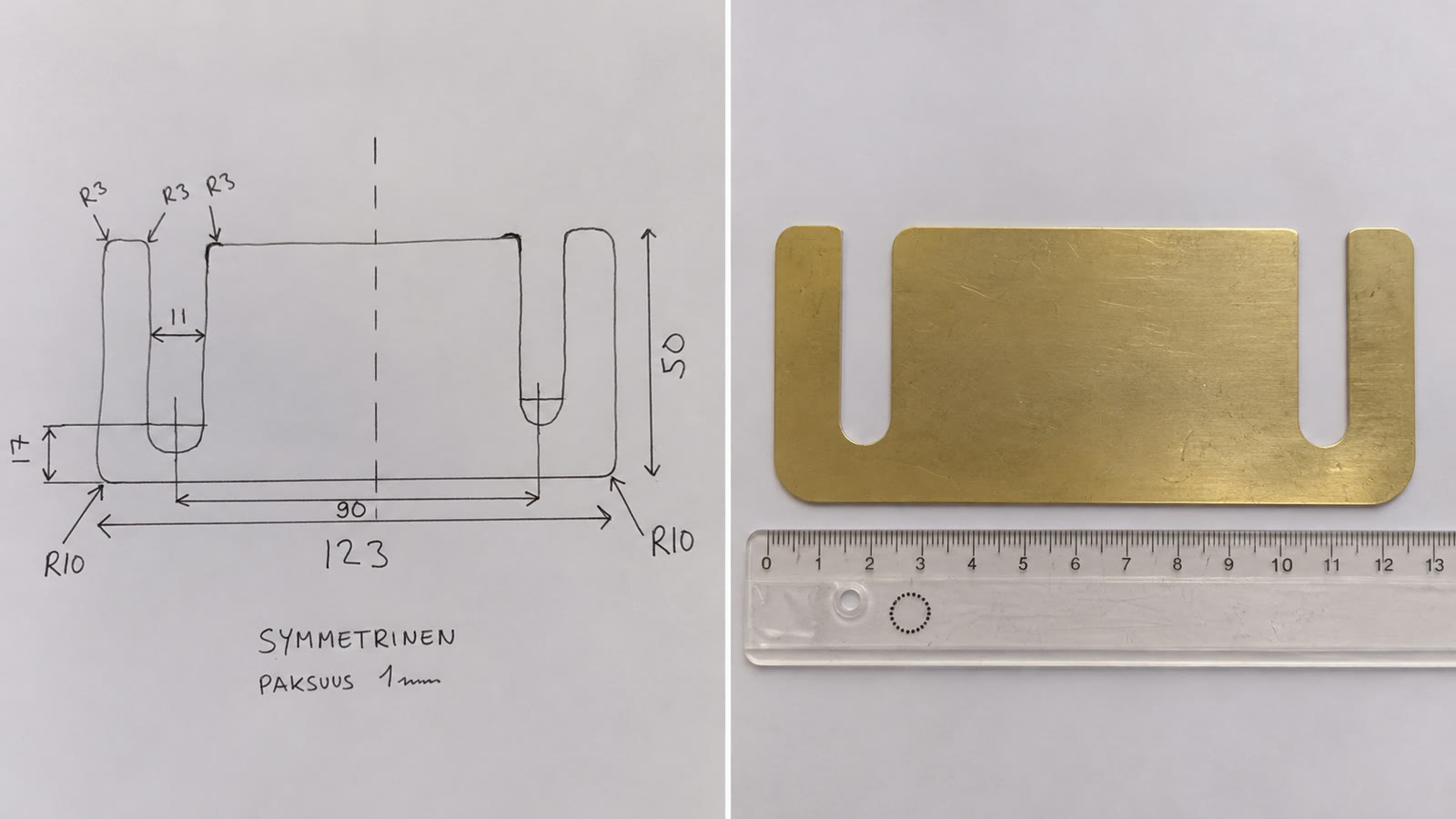
From sketch to workshop part.
Email a virtual company. Receive CAD files.
A virtual company with its own email
I set up my own virtual company on a remote computer using Codex and Paperclip. It has its own email account and is led by a CEO agent named Winston. I can email Winston a task and receive the results as files. This experiment connects that workflow with my own mechanical engineering experience.
A task starting on paper
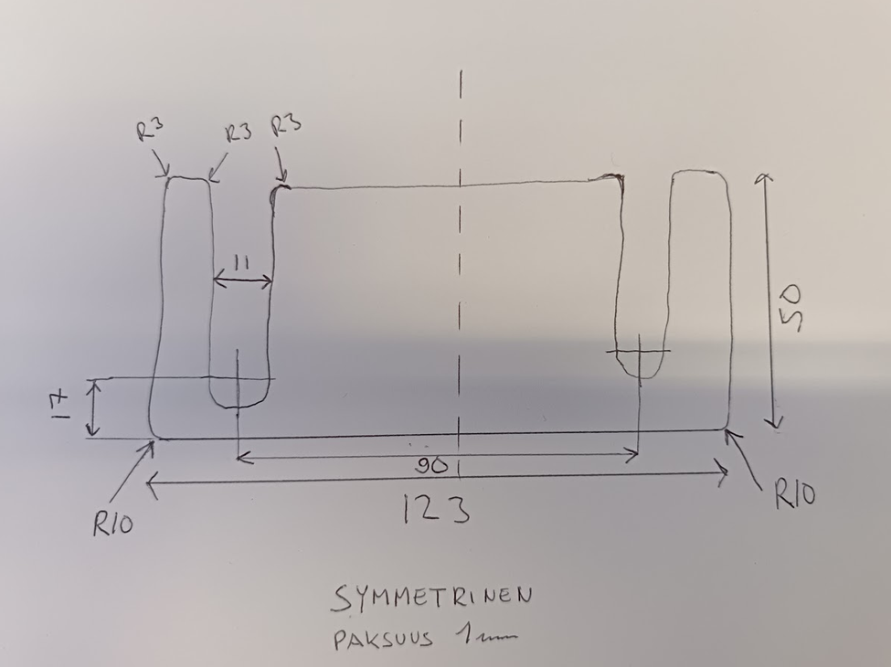
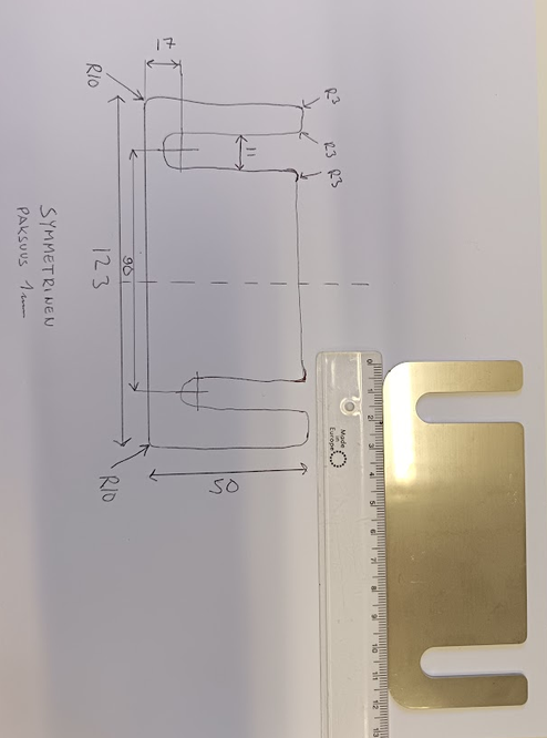
I needed a symmetrical shim plate for installation work, measuring 123 × 50 mm and 1 mm thick. I drew the part and its dimensions on paper, photographed it and emailed the image to Winston. I requested two deliverables: a STEP-format 3D model and a DXF cutting profile for manufacturing.
The agent’s tools
The virtual company’s toolset includes FreeCAD, an MCP connection and modelling skills. Winston had modelled an earlier part in FreeCAD. The experiment presented here resulted in CAD files based on a hand-drawn sketch. The key to the workflow is giving the agent a clearly bounded design task and specifying the required deliverables in advance.
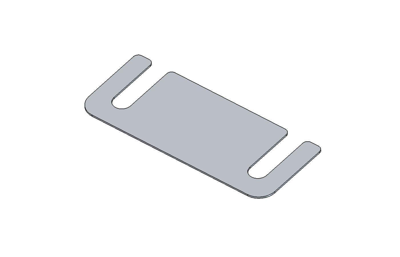
Files and interpretations returned by email
Winston returned the STEP model and DXF file by email. The delivery also explained how an ambiguous 17 mm dimension had been interpreted: as the height of the centre of the arc at the bottom of the slot. The DXF was delivered in millimetres at 1:1 scale with a closed cutting profile. Stating the interpretation helped me focus my own review.
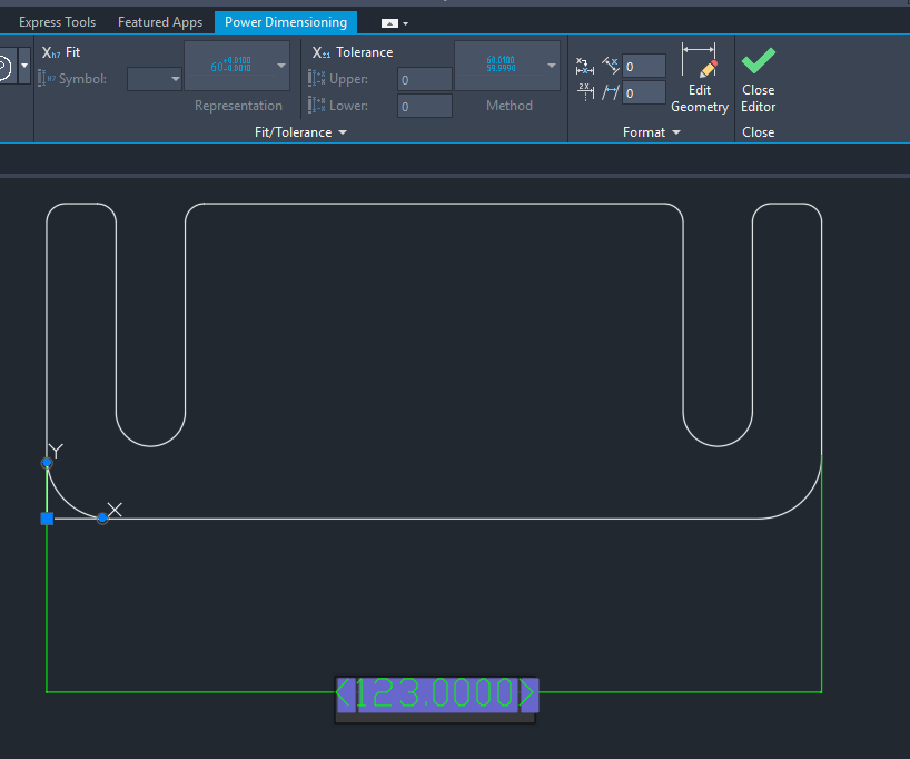
From model to laser-cut part
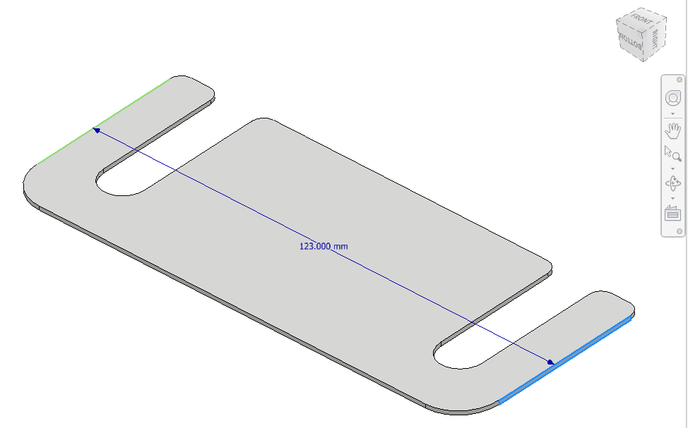
I opened the STEP file in Inventor and checked the model before manufacturing. The DXF was used as the laser-cutting input. The result was a physical shim plate that can be compared with the original paper sketch. The complete workflow moved from a hand-drawn requirement to digital files and a finished part.
My role
I built the virtual company’s working environment, defined the part’s purpose and dimensions, and assigned the task. I checked the delivered model and approved it for manufacturing. AI performed the work of producing the CAD material, while my mechanical engineering experience helped me assess whether the result met the requirement.
What the experiment demonstrated
A simple email can serve as an interface for assigning technical work to an AI agent. This completed example shows potential for bounded, recurring CAD tasks: provide clear inputs, make interpretations visible and have a person check the result. One successful part does not establish accuracy or time savings across all modelling tasks, but it provides a concrete basis for further experiments.
Tools
- Codex
- Paperclip
- FreeCAD (earlier experiment)
- Inventor
- STEP / STP
- DXF