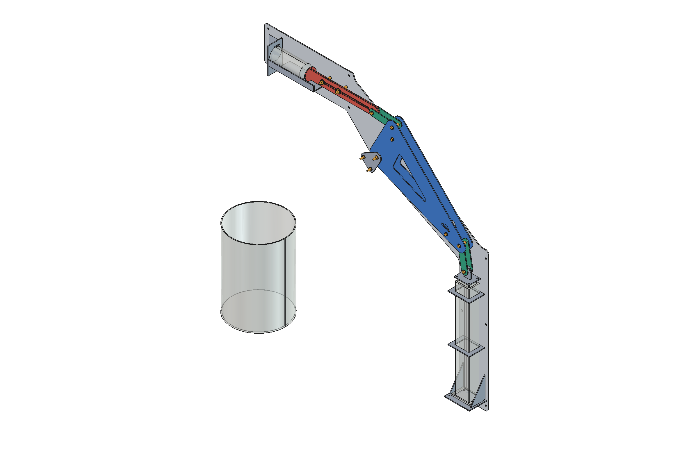
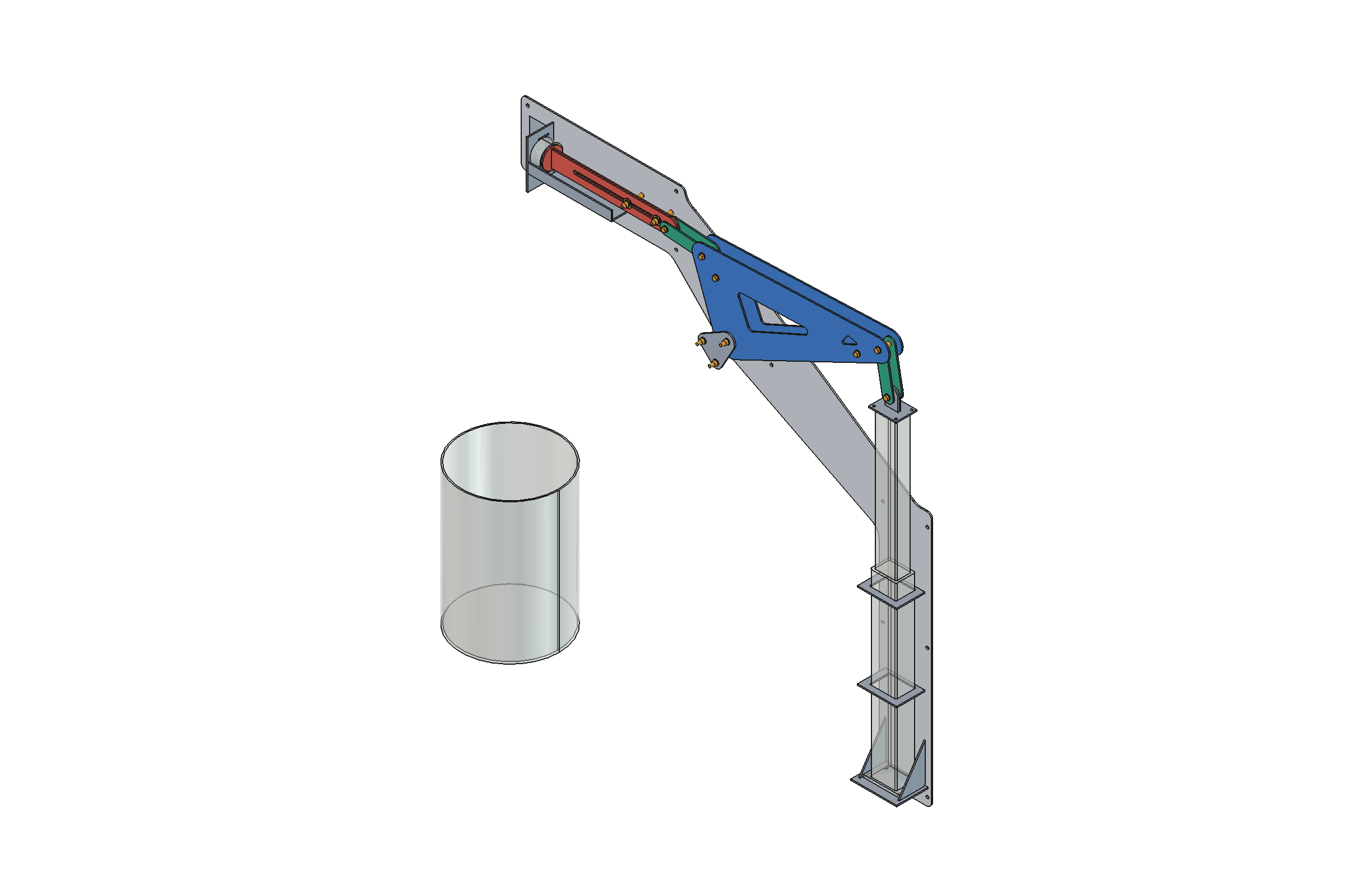
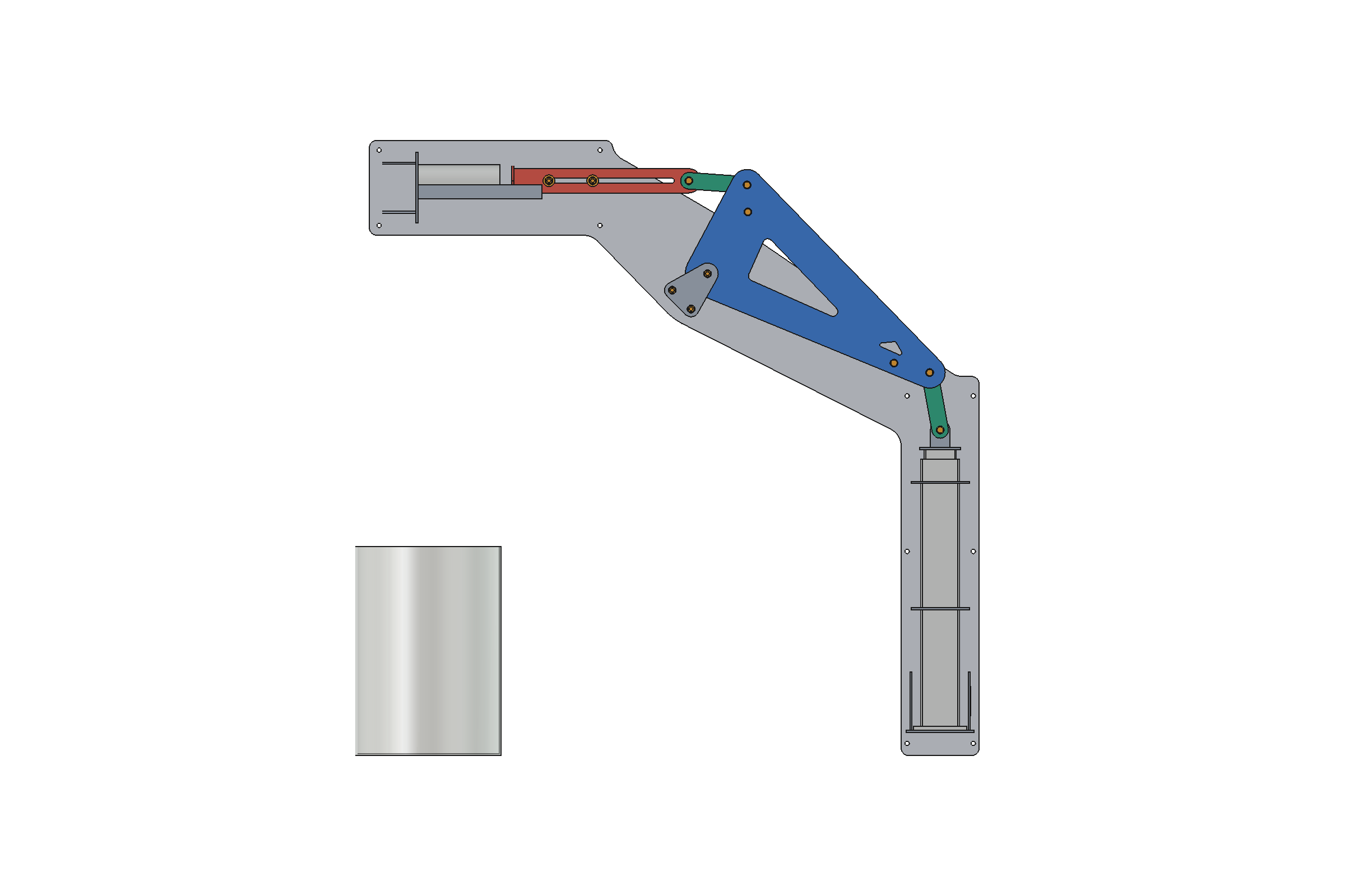
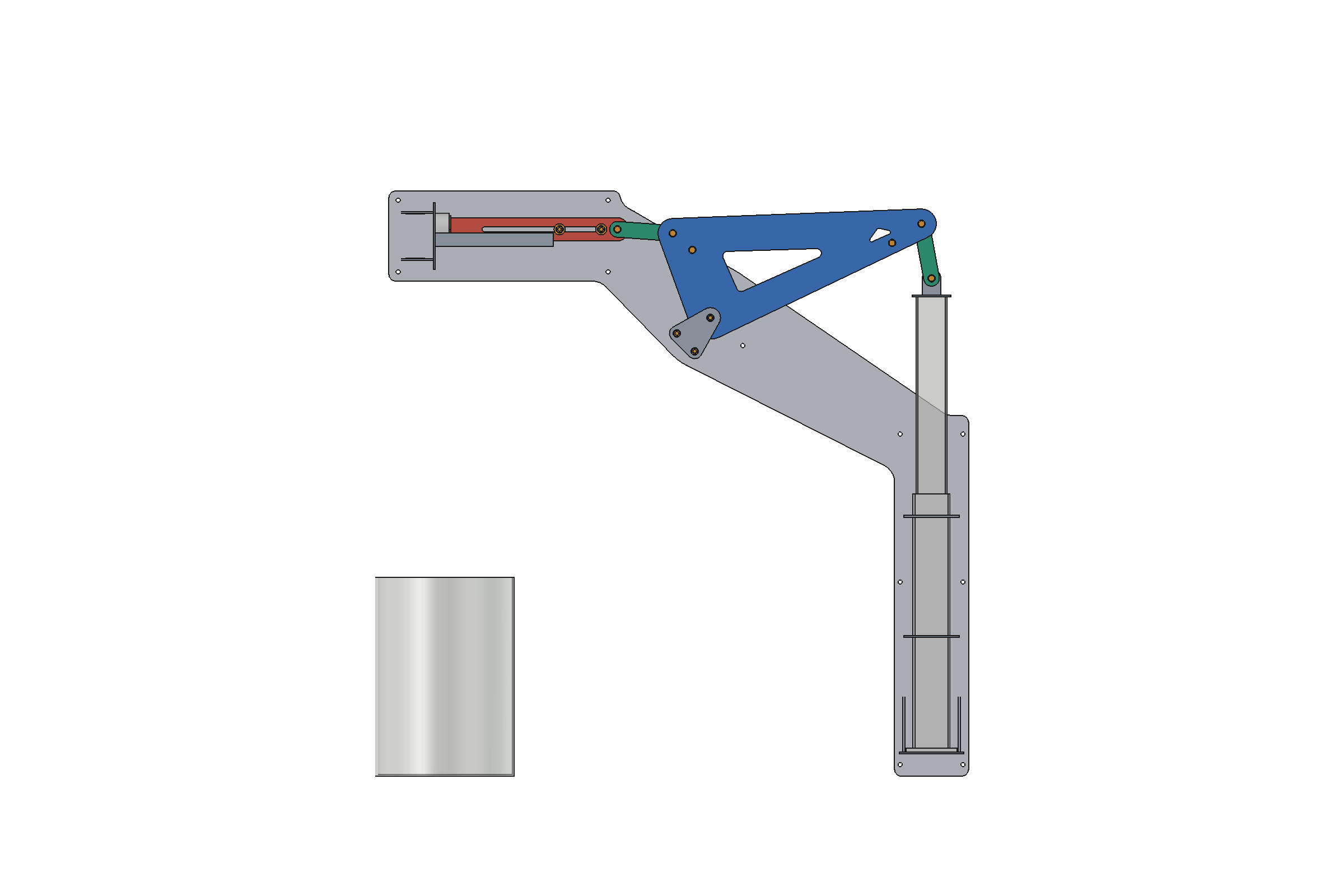
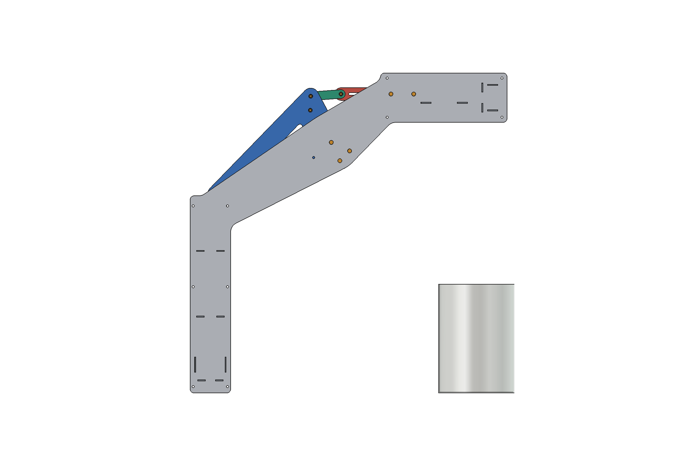
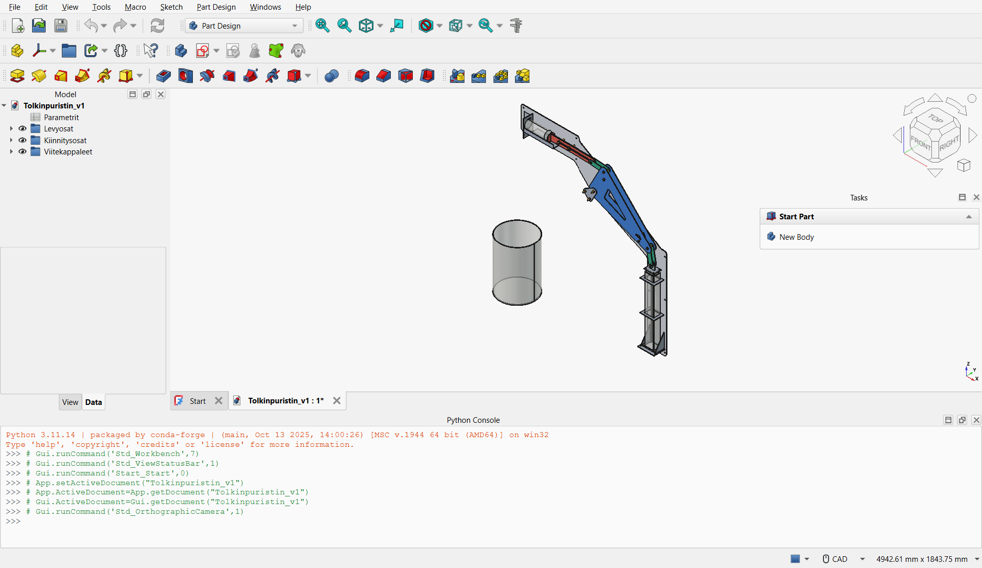
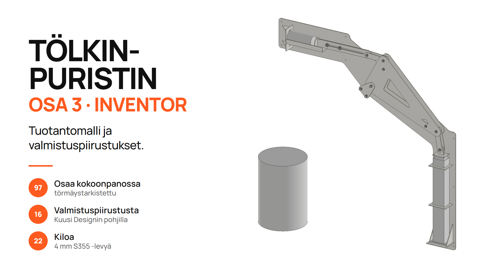
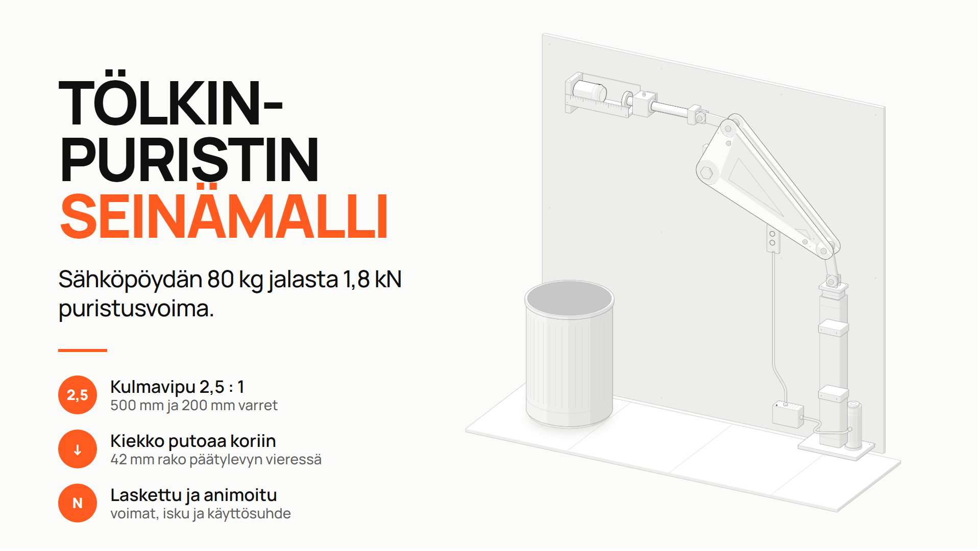
Can crusher, part 2: ready for manufacturing in FreeCAD.
From a concept figure to 15 laser-cut parts and a STEP model in open-source FreeCAD.
Goal
The part 1 figure shows how the mechanism works. A workshop, however, needs files. The goal was to turn the concept into a 3D model and cutting files with free FreeCAD.
How the model was made
Claude drove FreeCAD with Python scripts. All dimensions are in one specification file, and the script builds the whole model from it. When a dimension changes, the model is rebuilt in one run.
Structure
All parts are 4 mm S355 plate. The joints use a tube bushing and a through-bolt, so no bearings are needed. The ram is two laser-cut plates.
Strength
Claude calculated the critical points and corrected the structure. The bolt torque was limited to 8–10 Nm so that the bushing does not crush. The main pivot became a housing so that the bolt does not bend. Gussets were added to the end plate and the leg shelf.
Result
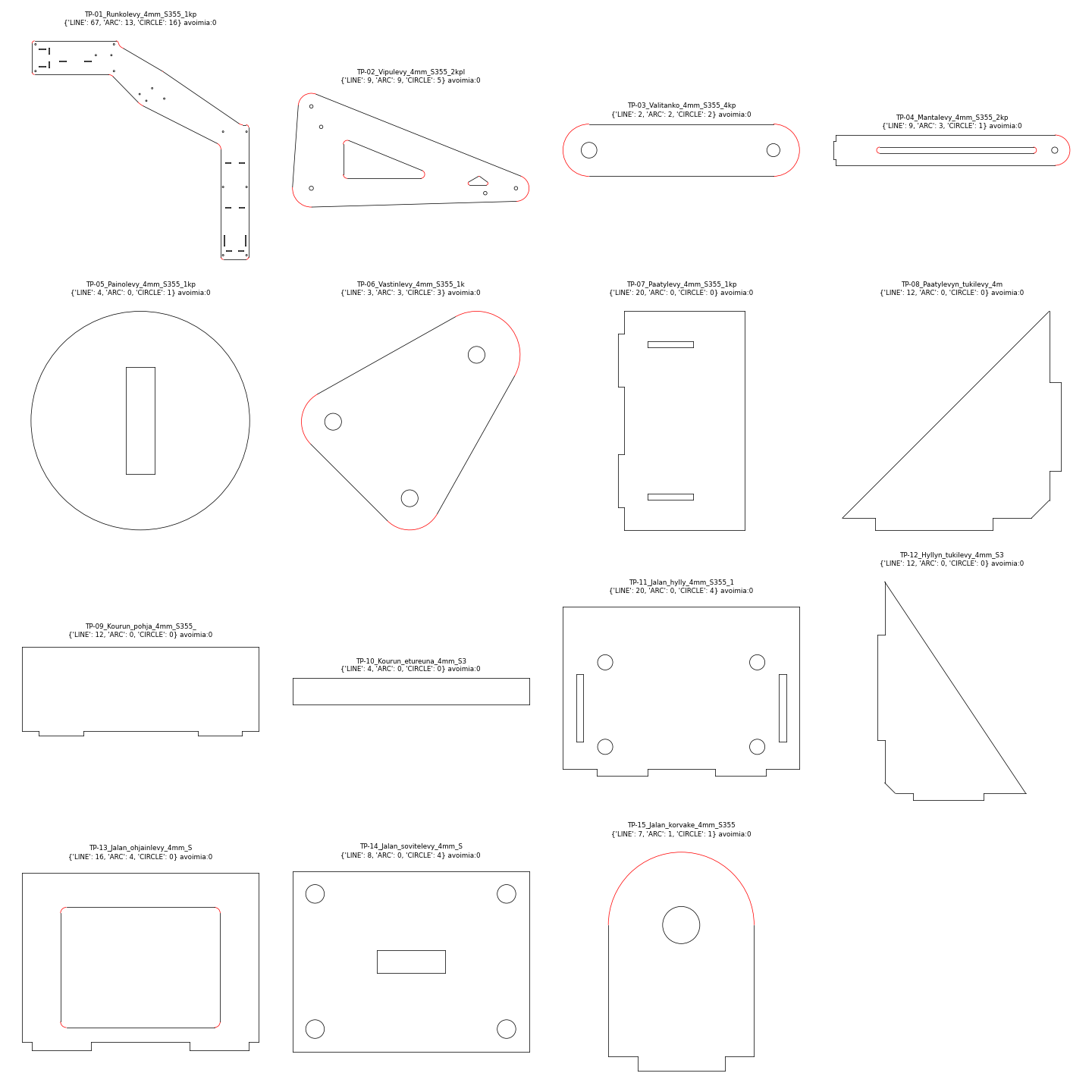
The result is 15 laser-cut parts (22 pieces) as DXF cutting files, the whole structure as a STEP model, and a parts list. The parts fit in less than half of a 1500 × 3000 mm sheet. Claude checked the model itself: no collisions over the full stroke, and every outline is closed.
My role
I made the structural decisions as a mechanical engineer. The AI did the geometry, strength calculations, model, cutting files and checks. The device has not been built yet.
Where the same technique can be used
Design of prototypes and small machines. Quotations that need cutting files for pricing. Teaching. No commercial CAD licence is needed.
Tools
- Claude Code (Claude Opus 5.5)
- FreeCAD 1.1
- FreeCAD skill (freecad-scripts)
- Python
- JSON specification
- DXF and STEP
More project images.